
Electronic Safe version 2
|
Electronic Safe version 2 | |
Previously I modified a cheap electric safe to work with an Arduino, and with the right software it could be used with sites like Emlalock or Chastikey. I provided this software.
But because my build skills aren't the best, I kept getting serial port issues, and more than once needed to get to the emergency key to open the safe.
So I wondered if I could do better. This time using an ESP8266 board, which provides WiFi access. No serial ports, and the board can host all the software.
I had also been asked if some of the cheaper safes might be convertable.
This is the safe (Amazon link). It's about $30 from Amazon. The model I bought was 'cos it was $2 cheaper, but there's a lot of identical models on Amazon.
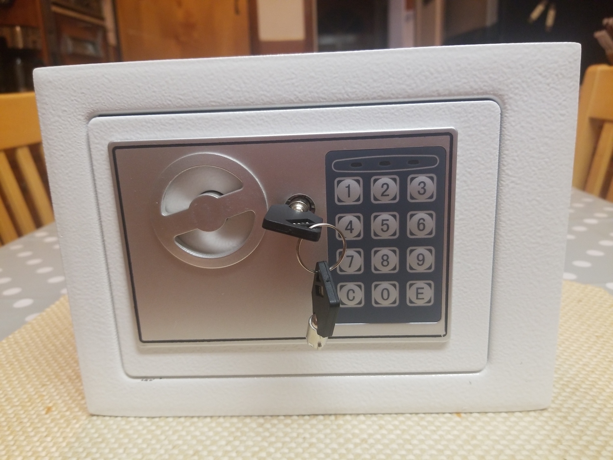
(note: many of these pictures can be clicked on to see larger)
This is the inside of the safe. The red button on the left is what you would press to reset the combination. But we're interested in the two screw holes. A standard phillips head will let you remove these two screws.
You also need to remove this screw. At this point the cover can be removed. It's a bit tight because of the rubber plug that's there to stop the door rattling, but a bit of brute force will get it out.
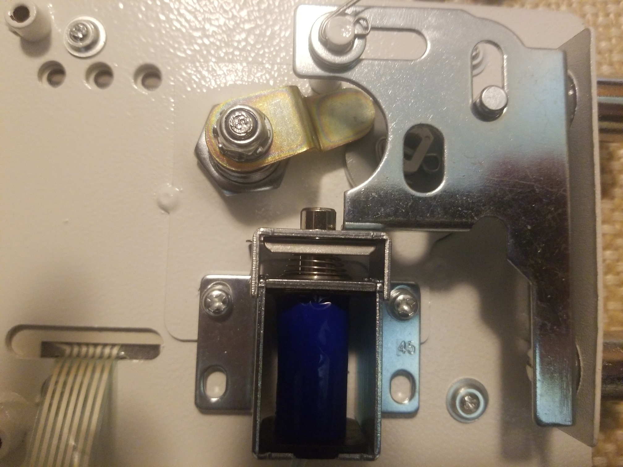
And this is what the internals look like. The magic is the blue solenoid. In the "down" state it lets the locking gate slide sideways. And that's how this type of safe works; the key (as shown in this picture) pushes down on the solenoid. The electronic part activates the solenoid and that lets the gate slide.
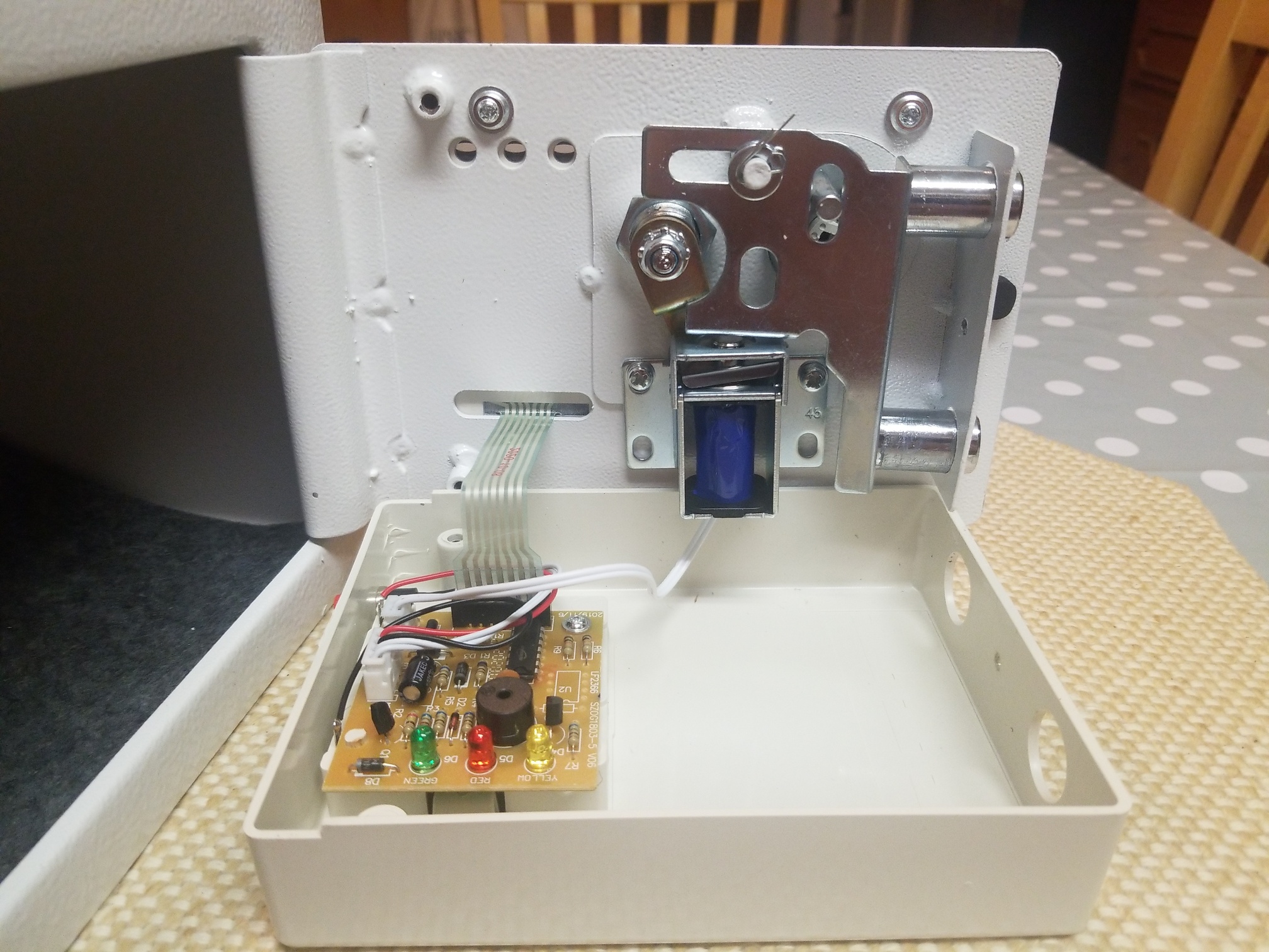
This is what it looks like in the locked position.
The only cable we care about is the two wired to the solenoid.
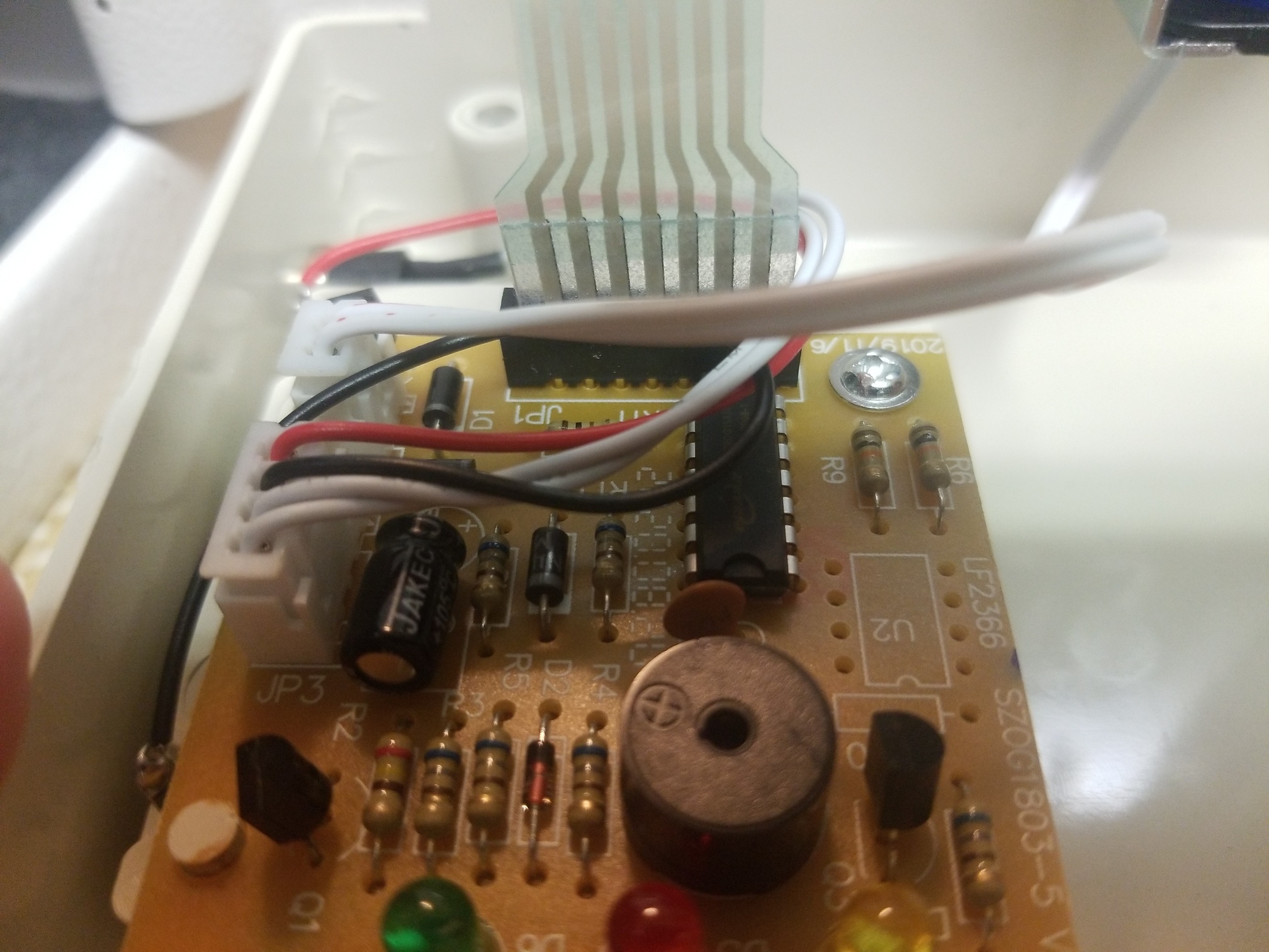
Disconnect those from the board. FWIW the other 4 wires handle the power (red/black) and the reset button (white). We don't care about these, though; we only want the two wires to the solenoid. So carefully unplug that cable. That's it!
At this point we could remove the circuit board, but let's leave it in place. We can always revert the changes and switch the safe back to normal operation just by plugging the cable back in again.
NOTE: This solenoid is especially easy to "bounce" by banging on the safe; the spring is very weak. That means that the right timing of banging on the top and turning the handle might open the safe. This isn't high security! (The key lock also isn't high quality). Increasing the security of the safe isn't part of this instruction!
Annoyingly it's not clear what the solenoid is. The blue wrapper blocks all data. So how much power does it need? We know it can work on 6V ('cos of the 4 batteries) but how much current does it need? I measured the resistance (15ohms). At 6V that'd be around 400mA which made me wonder if the Vin line of the NodeMCU would be sufficient. And... it wasn't. It was enough to hold the lock open but it wasn't enough to cause the solenoid to activate. So we're gonna need to be more innovative about powering the system.
So let's look at designing the replacement.
For power, let's use a MOSFET as a relay. I used a RFP30N06LE becuase this can be triggered at 2V and so the 3.3V output from the NodeMCU should work.
Note: looking at the front (with the writing facing you and the
pins downwards) the 3 pins are:
Gate Drain Source
Source will be connected to ground, drain will connect to the solenoid, and gate will connect to the NodeMCU pin we use to trigger this. The other pin of the solenoid will connect to the power. Now when the gate line goes high the solenoid will trigger.
Finally there's a 4k7 resistor between gate and ground. This is a pull-down resistor just in case the ESP-12E pin floats. It's possibly not needed, because the software drives the pin high or low and if the software crashes then the watchdog timer will reboot it pretty quickly, but I put it there just in case.
That all sounds complicated! Now to work out the best placement for a veroboard so I can solder it all together. Which appears to be:
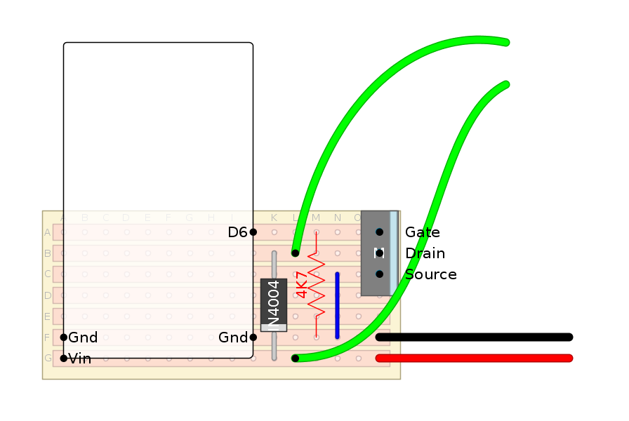
That doesn't look too complicated. One diode, one resistor, one MOSFET, a few cables, and some pins.
Proof of concept prototype. This is powered by a 9V battery, which won't be the final solution! I removed the solenoid from the safe to make it easier to test.
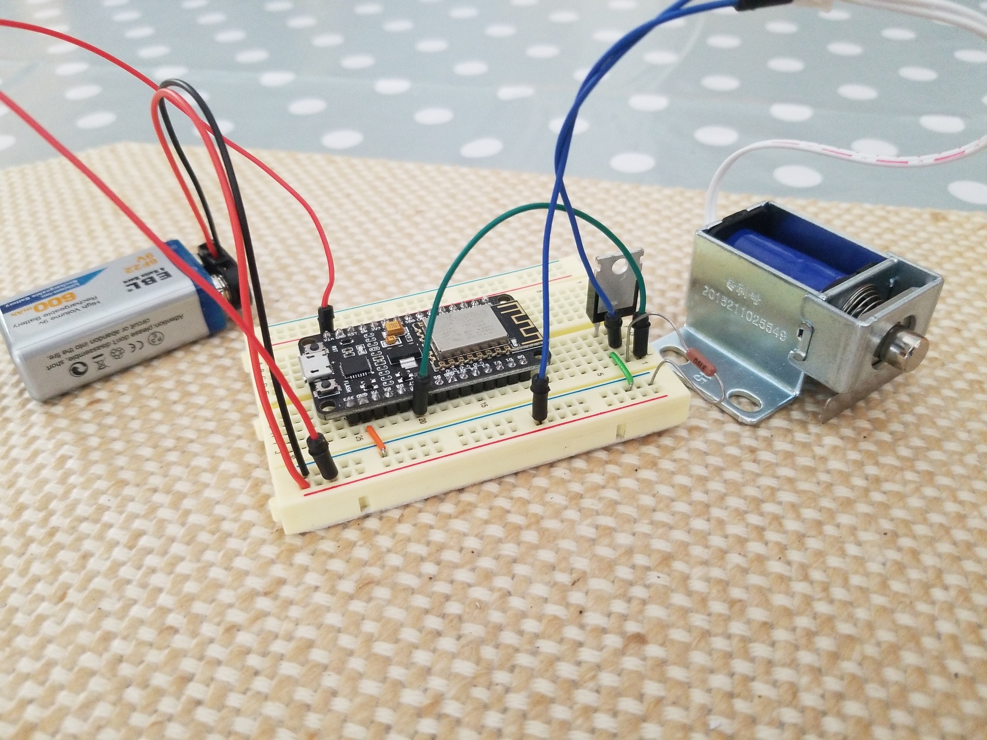
(there's no diode here; I added it later! And if you're looking carefully the resistor is in the wrong place. Apparently I got lucky and didn't destroy the MOSFET... Also shush spot the cable from D7 when the diagram says D6. You didn't see that!)
In this setup I can do
curl http://safe.local/safe/?open=1
and the solenoid will open for 5 seconds. And... it worked!
In this case I used an NodeMCU ESP-12E even though it's overkill and overized. You could use a WeMos D1 Mini or clone and it would work just a well. However the D1 Mini will only take 4->6V input, whereas the NodeMCU ESP-12E can take up to 10V (maybe even 12V). That gives us more flexibility in the power supply we use. I did my testing with a 9V battery, which wouldn't have been possible with the D1 Mini.
Note that D6 on the ESP-12E "conveniently" lines up with the Gate on the MOSFET. Not like I planned that or anything, honest! (Confession I had planned on D7 being the pin but I counted wrong and D6 it is. Which is why the proof of concept used the wrong pin. Oops!).
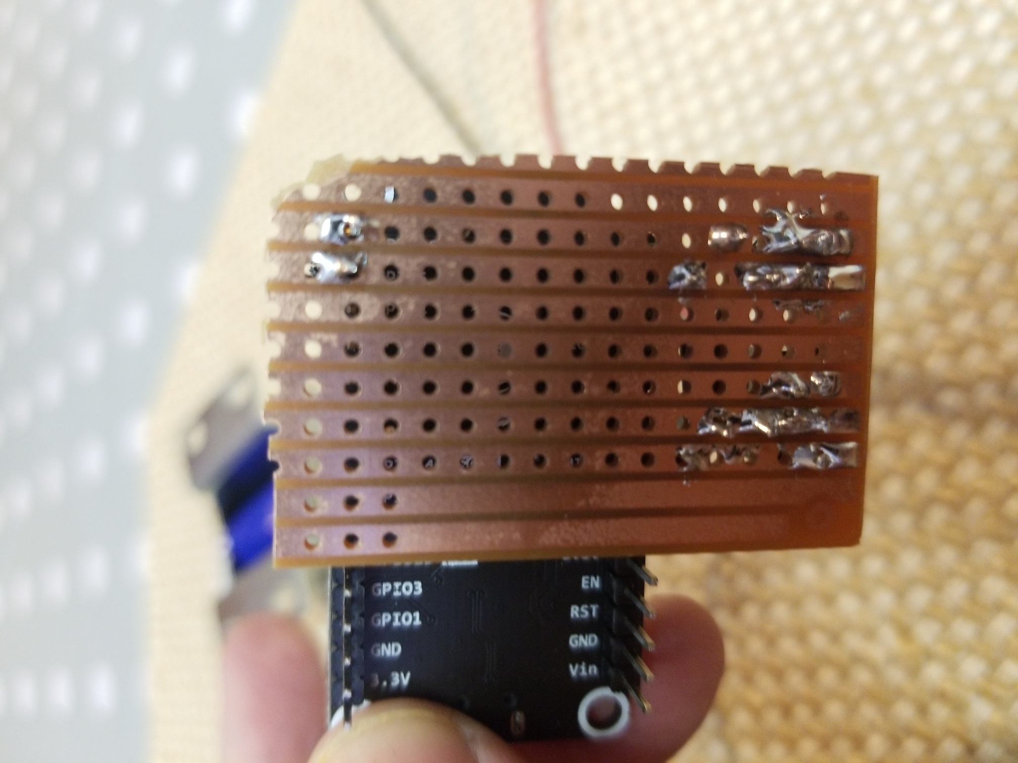
Now I wanted to use a "socket" like approach for the ESP-12E so I could remove it for software upgrades. This just required 3 pins (GND, Vin, D6) but I used 4 (the second GND) to add a bit of stability. This turned out to be one of the harder parts because I couldn't find any single-pin sockets that are big enough to handle the standard pins. I ended up cutting up a 40pin strip, and that's not very tidy... but it worked. (In the second of these boards that I made I used a couple of 8 pin strips and cut the pins off and covered the gaps with insulation tape; that also worked and was easier to handle).
I also put a couple of normal pins on the board to make it easy to connect to the solenoid via normal male->female connector cables, and I soldered relatively thick power cables that can be connected to the power supply.
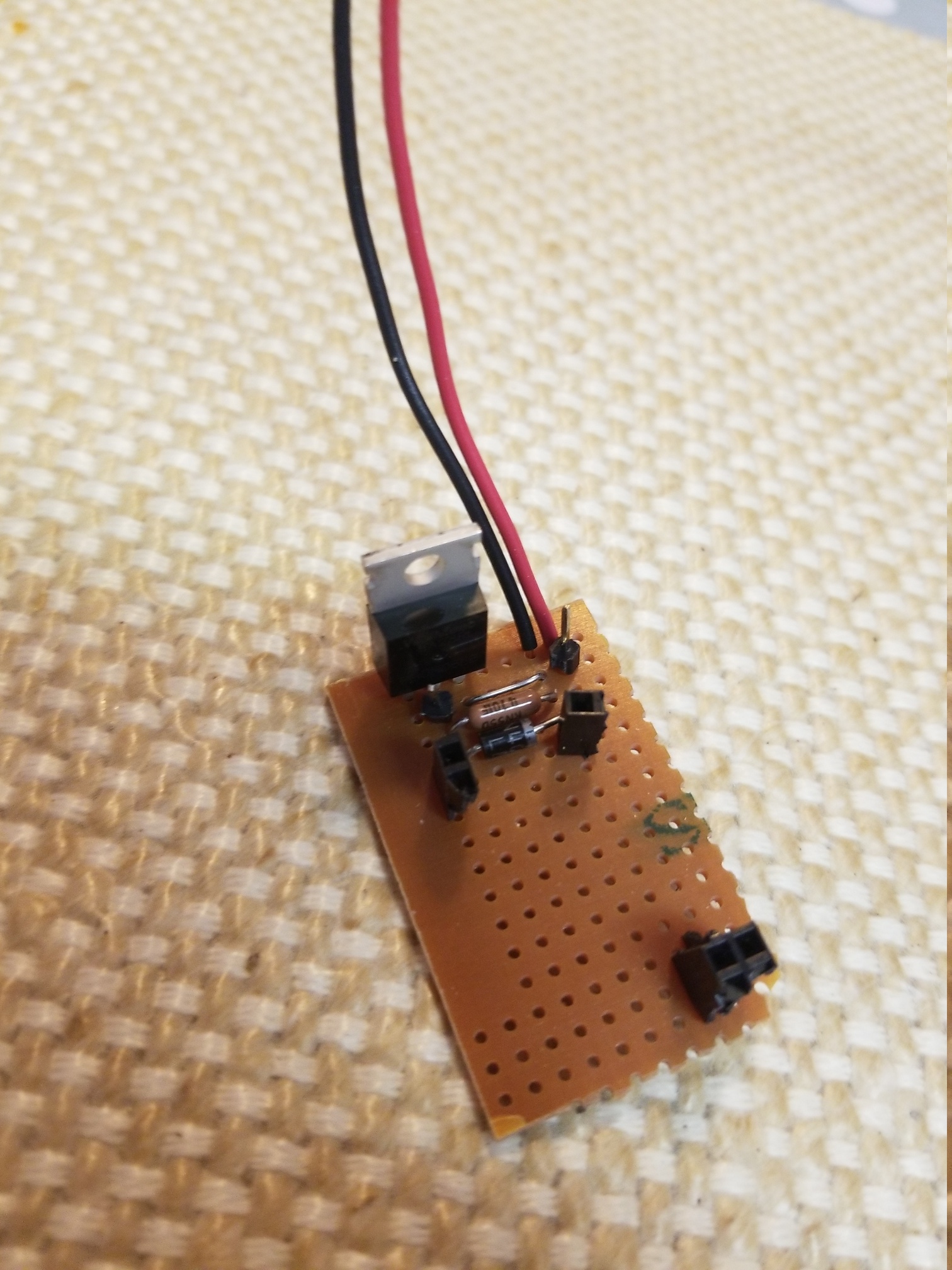
(and yes the resistor is still in the wrong place! but at least the diode is there, now)
And this is how it looks with the solenoid connected and the ESP-12E inserted.
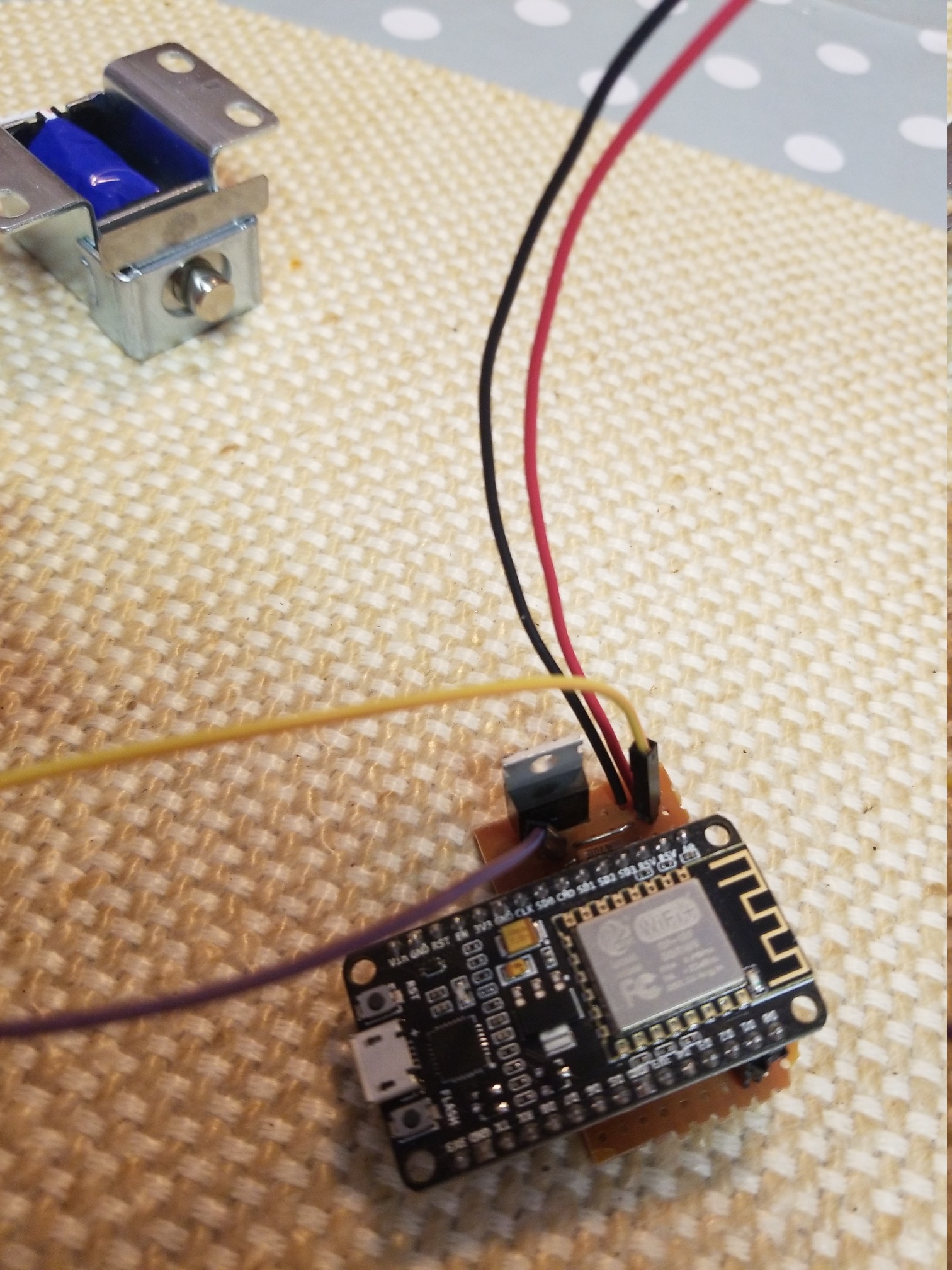
My soldering skills still aren't the best... but, at least it works!
Unfortunately there's not enough space inside the safe cover on this small safe (the old large safe had plenty of free space) so now we get to the mounting part.
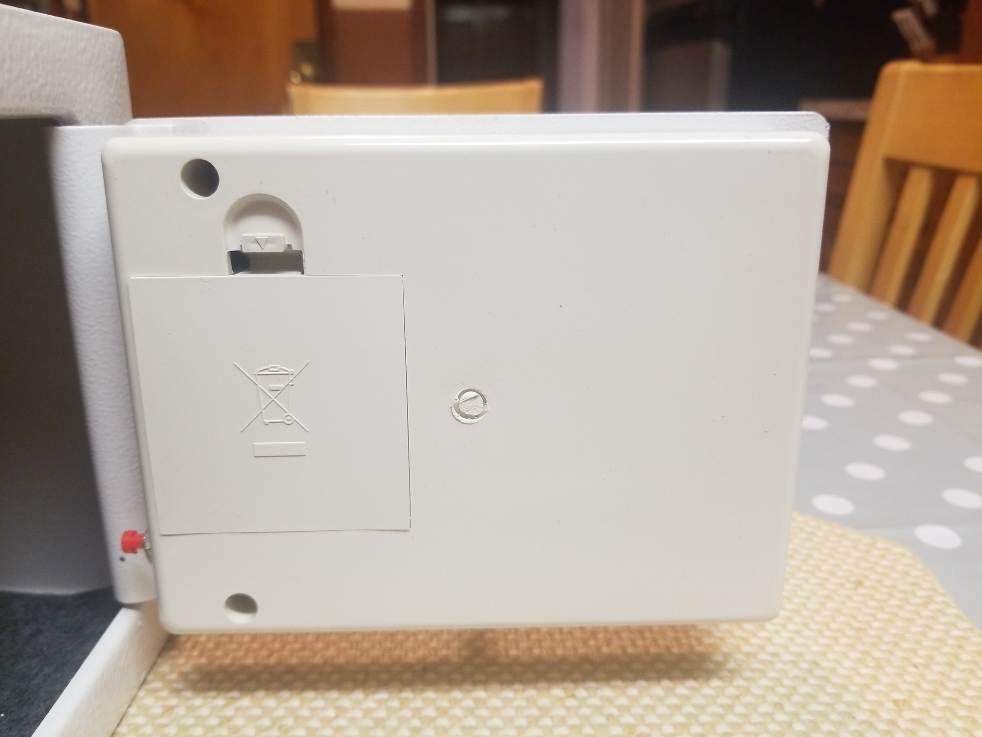
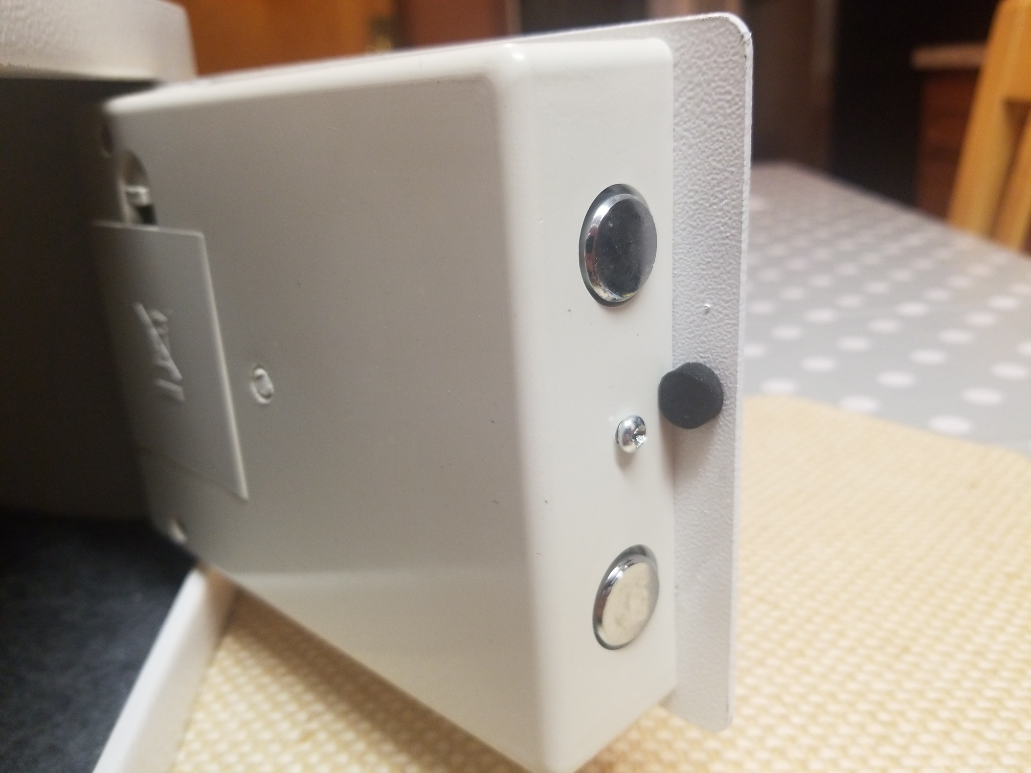
To run the solenoid cables from inside the safe cover to outside it I cut a small hole near the top of the battery door. Just big enough to slide the two wires through. This is the only real change to the safe.
I connected two "dupont compatible" male-female cables to this connector.

Mounting of the whole thing was... done by duct tape. Yeah not very professional but it seems to work.
Importantly I taped down the power wire so that it didn't flex whenever the door was opened/closed. This means the wires shouldn't snap off the board. Whenever movement happens it can stress solder joints, so we want to prevent that as much as possible. Let the tape take the strain!
And the ESP-12E just slots in, nicely. It's easy to remove if software updates are needed. Just be careful to align the pins correctly when you plug it in.
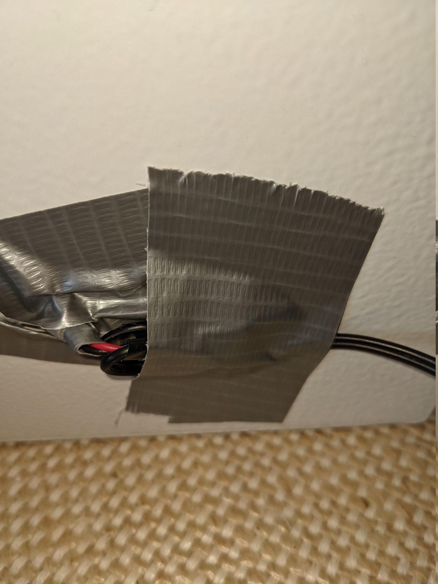
Now the power cables can feed out of the back of the case. I was worried that the relatively thin metal could rub and end up damaging the cables so I protected them with some more tape. And I taped the wire to the top egde of the box. I didn't do a very good job, really. Not pretty... but it works!
And then out of the back I added more tape to try and keep it in place.
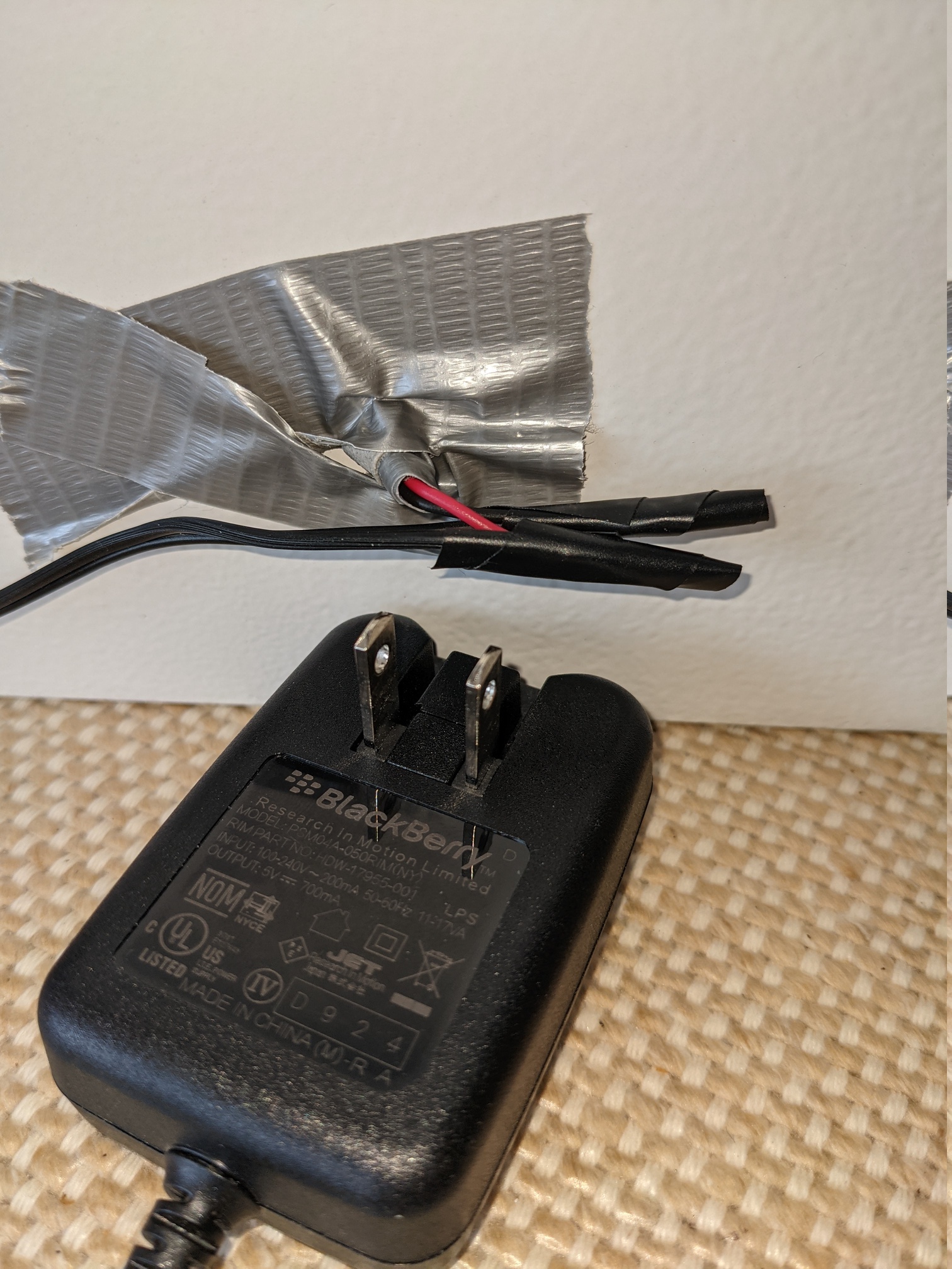
Powering this safe can be done pretty much from any DC power supply from 5V to 10V (maybe up to 12V). I had a really old Blackberry power supply (I never had a Blackberry, so not sure where I got it? Maybe from a "junk" bin at work). This is 5V 700mA. Plenty. I cut the tip off and conneted the wires up.
It's very important to ensure you get the +ve side connected to the +ve input to the board, because the ESP-12E may not like reverse voltages. This power supply didn't make it obvious which wire was +ve so I had to use a multi-meter. But once I knew which was which it was simple to connect.
And to protect this also from movement I stuck it to the back. Lots of duct tape used in this build!
And that's it! The safe is built.
This software can be built with the standard Arduino tool set with the esp8266 libraries loaded.
A prebuilt ".bin" file is included that can be loaded onto an ESP8266 with 4M RAM (I tested with a NodeMCU ESP-12E; it should also work with a D1-mini and maybe others).
The safe is modeled with some simple states:
When the safe software is first loaded it will create a WiFi Access Point called something like "Safe-123456" (the exact name will depend on the MAC address of your board). You should connect your phone or laptop to that access point.
This will let you go to http://192.168.4.1 or (if you're lucky) http://safe.local and that will display the WiFi configuration screen.
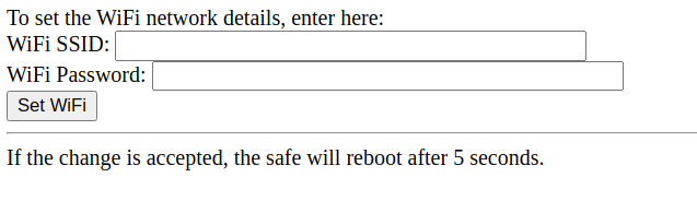
Enter your WiFi SSID and password. In 5 seconds the software will reboot and the safe will connect to your local network. It will attempt to get an address by DHCP.
If it is unable to connect to the network after 60 seconds then it will give up and start up the Safe-123456 access point again and allow you to change the network details and try again.
Once the safe is on your network it will broadcast the name "safe.local" via mDNS (aka zeroconf, Bonjour, Rendezvous). If your machine supports this then you should be able to go to http://safe.local otherwise you may need to check your router to find the IP address that was assigned to it.
Opening the web page in a browser should give you a menu on the left and a larger status box on the right.
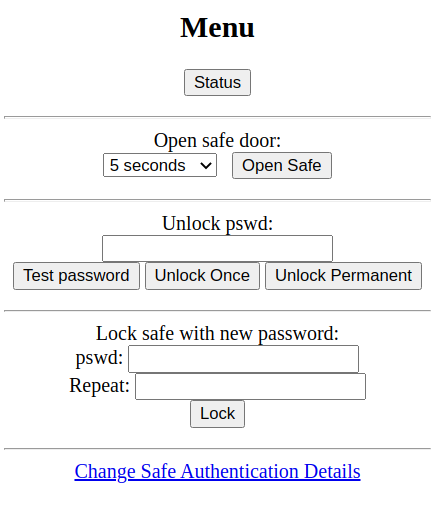
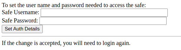
The first thing you should do is go to the "Change Safe Authentication Details" link at the bottom of the menu. Here you can set a username and password for your safe. It's recommended you do this so that only authorised people on your network can reach this interface. After setting the password you should be prompted to login before doing any more work.
On the menu you will see various options:
Passwords can be up to 100 characters long. Although I've tested with a few special characters (eg. % and &) you should verify the password with the "Test password" function before closing the safe door!
Although the software wasn't designed to provide an API, all the access is via HTTP requests and so can be performed from the command line (eg curl).
The format is
http://safe.local/safe/?command=1¶meters...
The /? are important.
Of course you need to provide the username and password.
So to get the status:
    curl -u user:pass http://safe.local/safe/?status=1
    Safe is unlocked
Commands you might use:
    ?open=1&duration=<time_in_seconds>
    ?lock=1&lock1=<pswd>&lock2=<pswd>
    ?pwtest=1&unlock=<pswd>
    ?unlock_1=1&unlock=<pswd>
    ?unlock_all=1&unlock=<pswd>
Note that "lock" needs the password sent twice 'cos it checks the two
match.
Now you might think "if I can send unlock_all requests in a program then I can write a loop to test them all".
Yes... but, good luck! An 8 digit numeric password has 100,000,000 combinations. Let's assume you get it right half way through. 50,000,000 attempts. Each attempt takes 2 seconds 'cos the safe code enforces that. That's around 3 years. And the password can be digits and letters and more. You might get lucky! But don't bet on it...
If you're a Chastikey user and want to do "dual" locks (where the lock is held by two keyholders) then you can easily make each lock 8 digits long... so the result is a 16 digit combination. You'll definitely be locked until both keyholders release you!
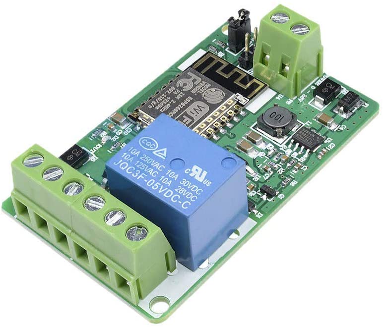
On these boards the relay is typically connected to D4. You'll obviously need a USB->Serial (3.3V!) programmer to program this type of board since they don't come with their own serial interface. But the sketches I provide should work with it with just the pin change.
This is probably a easier option; no soldering necessary. A little bit more hassle to program the device, but a lot cleaner!
This has been built as version 3.