 |
Electronic Bondage Safe for Emlalock
|  |
For a number of years I had one of these cheap electronic safes. They allow
for a combination to be set. They're battery powered.
I bought this one from Harbor Freight in 2004:
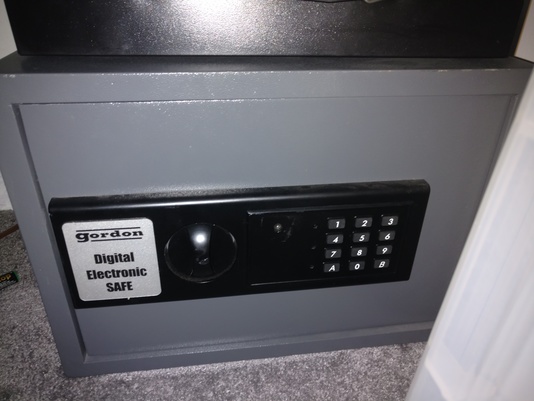
I made some minor changes to it; basically ran a power cable in through the
back, and hooked a power adapter into the battery terminals. This meant
I could use a normal mains timer and lock the safe for a period of time
(no power meant I couldn't open it!). Because these things can lose their
combination if without power for too long I also extended the reset button
to poke out the back (after power comes back I can reset the combination),
and also an LED so I could see if the power was on. And I made it so the
safe could be returned to normal use, so my Lady could set a combination
and lock it, and then let me know the combination at some time in the
future.
This post isn't about that safe though.
About 10 years later the safe started to stop working; the control panel
stop responding, it made horrible noises... one time I thought I was locked
into a maids outfit and heels with the safe not working and the emergency
key over a mile away at my Lady's house! Fortunately anger lifting and
dropping the safe got it working again long enough to free myself.
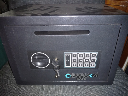
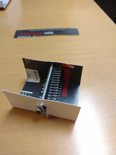
So I bought a new safe. I got this one from Staples
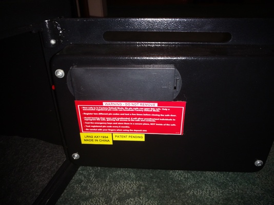
I was about to make similar changes to this safe, when I noticed the internals
looked very very similar!

When I looked closer, the only difference between the two setups appeared
to be the connector to the battery/reset switch had the alignment notch on
the other side (the white connector in the picture). So I did a little kludging and put the new safe's board
into the old safe. And it worked! The old safe is still in use, with
the new board.
So I had a safe with no electronics. I wondered if it was possible to
replace the electronics with an Arduino, and set complicated passwords
via a computer. Ideally this would be able to talk to Emlalock to create
a session. Now I could be locked up with no knowledge of the combination
at all.
And that is what this post is about!
Requirements
- An electronic safe. Pretty much most of these safes use the same
technique as the two I have. We don't care about the front panel or the
electronics; all we need is the solenoid locking mechanism.
- An Arduino Nano. These can be found on Ebay for a few dollars
- An Arduino relay. The Solenoid needs more power than the Arduino can
provide, so we use the Arduino to switch a relay, and this switches power
to the safe. I found one for $4.
- A DB9 female serial port plug. This is how we communicate to the safe.
- A USB serial adapter. These are also on Ebay for a few bucks. Doesn't
need to be expensive! Indeed the cheaper ones are normally better; the real
RS232 standard allows for voltages up to 12V, which is more than an Arduino
can handle. But the cheaper devices tend to stick to USB voltage levels
(5V) which still works and is compatible with the Arduino.
- A 5V power adapter. I took an old USB adapter and cut the end off.
Overview of the solution
The Arduino will determine if the safe can be opened or not. It will be
embedded inside the safe. To talk to the Arduino we use a serial port
plugged into the PC. Using this we can send commands such as "lock the
safe with password 12345", "unlock the safe with password 12345", "open the
solenoid lock". The Arduino will save the password into its EEPROM so
even if the power is removed then applied later it will remember.
Originally I was going to use the USB port on the Arduino for both power
and communication, until I realised that this would let me upload a new
sketch and open the safe at any time. Doh! Fortunately there's a
software serial solution, so we don't need access to the USB port.
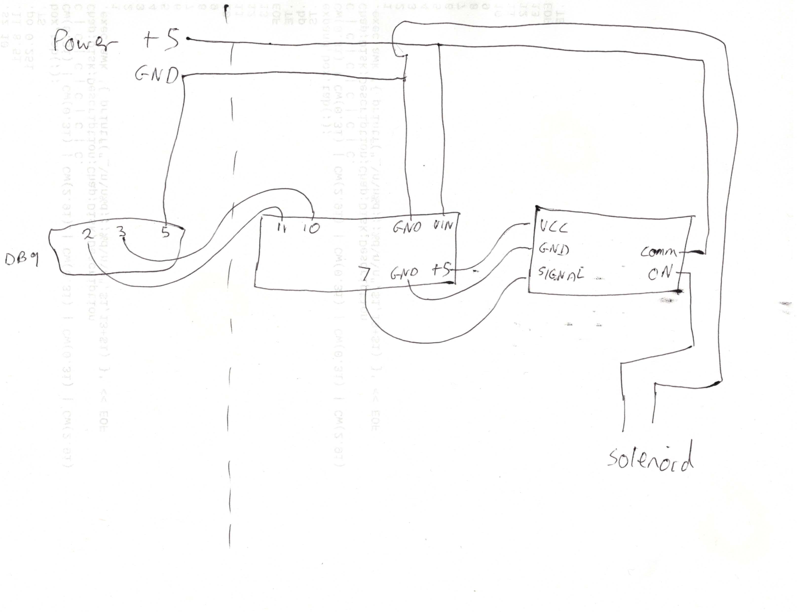
So this is what we're going to try and build (click for a larger
image). Sorry for the awfulness of my sketch!

Putting it together
-
First remove the inside cover of the safe. This is normally just 4
screws.
-
Unplug the power/reset cable from the main board. Unplug the solenoid
cable from the main board. Unplug the ribbon cable from the main board.
-
You can now unscrew the board from the safe door. We don't need it
any more.
-
The reset switch on the side of the door can be unscrewed and pushed
through. This frees up a nice hole, which we'll use later. If you
cut the two wires to the battery compartment then you'll be able to
remove that cable hardness as well. We don't need that anymore, either.
-
At this point you should have the door cover free and the safe door
has the ribbon cable and the wires to the solenoid.
-
We need to run a cable through a mounting hole on the back of the safe,
and then through the hole in the door cover. We only need 4 strands
of this cable (2 for power, 2 for serial).
I used a few feet of spare ethernet cable I have. It works well. The
unneeded 4 cables add strength and don't hurt.
- Now on the outside of the safe pick one of the twisted pairs (I used
orange but it doesn't matter). Connect them to the power supply. In my
case I just cut the USB end off an old LG USB power adapter and wrapped
the wires together. It's important to remember which side is +5 and which
side is GND, so I made 'orange' to be +5 and 'white/orange' GND.
- Pick another pair ("blue"). These will go to pins 2 and 3 of the DB9
connector. You also need to connect pin 5 (GND) of the DB9 to
GND of the power supply. I'm terrible at soldering so, for me, this
was the hardest part! This is also why I chose ethernet cable; the
thickness of the cable means it can be secured nicely to the DB9 and is
unlikely to break free.
- Take a break; we've finished on the outside of the safe. Now we're
starting on the inside
- The two cables used for serial communication need to be connected to
pins 10 and 11 of the Nano. Now I cheated a little, here. I took a standard
cable used to connect to Arduino pins and cut one end off, and connected
that to the ethernet cable. Now I can just slip the cable onto the pin.
If you're better at soldering than me then you could solder directly to the
board.
- The power cables need splitting; one set will go the Arduino (so
another pair of standard cables), the other positive side will go to the
input of the switched side of the relay, and the negative will go to
one side of the solenoid.
- We also need a connection from +5V, GND and pin 7 of the Arduino
to the logic side of the relay, and a connection from the ON switched
side of the relay to the other connection on the solenoid.
Now the reason I used standard cables is that I can put all this together
and test it (see later) and adjust cables as necessary. Once it's all
been proven to work we can then mount it.
Summary of connections
Arduino Nano pinout requirements
================================
 (See https://forum.arduino.cc/index.php?topic=147582.0 for a reference card)


                      +---------+
                      |         |
                      | o     o | VIN Power +5V in
                      | o     o | GND Ground in
  Ground to relay GND | o     o |
                      | o     o | 5V  5V to relay
                      | o     o |
                      | o     o |
                      | o     o |
                      | o     o |
                      | o     o |
   Signal to Relay D7 | o     o |
                      | o     o |
                      | o     o |
  Serial Pin 3 RX D10 | o     o |
  Serial Pin 2 TX D11 | o     o |
                      | o     o |
                      |         |
                      +---------+

Relay connections
=================
  Control side
     VCC - from  5V on Arduino
     GND - from GND on Arduino
      IN - from  D7 on Arduino

   Switch side:
     Central pin +5V power in
          ON pin to safe solenoid
                 (if the solenoid opens when the safe should be locked
                  you've picked the wrong side)

Solenoid
========
   (direction doesn't matter)
   +5V from Relay
   GND from power in

RS232
=====
   Pin 2: Connect to Arduino D11
   Pin 3: Connect to Arduino D10
   Pin 5: Connect to power ground  (important!)
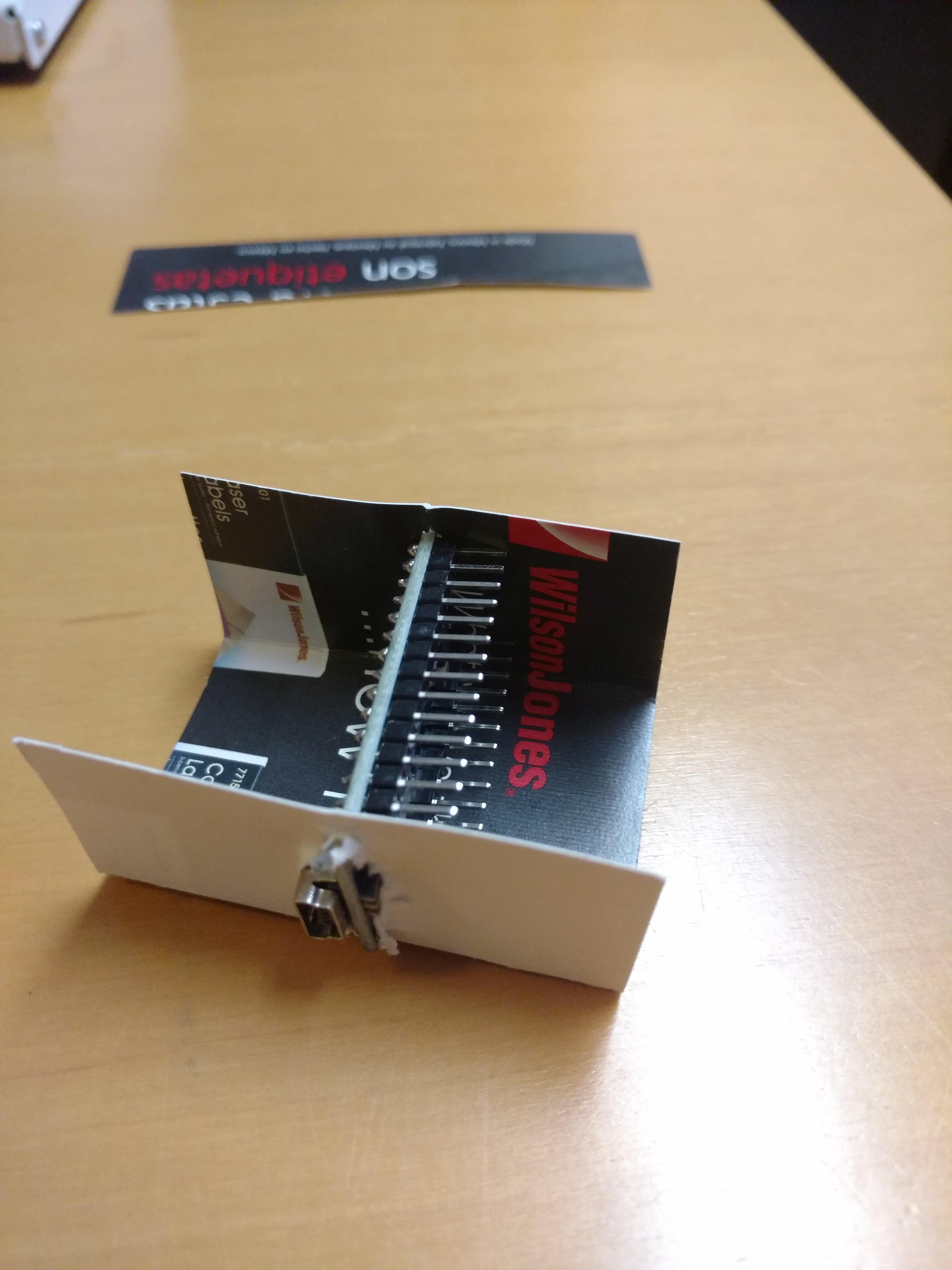
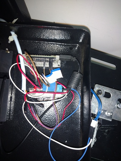
Mounting it
This kit is small enough that we can install it inside the cover. I wanted
to keep some air gap around the arduino and relay and I realised I could
mount them sideways. The easiest way would be to use some folded carboard!
If you're worried about the cardboard springing loose then you can
just put some tape around the ends to add some pressure.
Now I recently got a 3D printer, so I printed a couple of carriers
from thingiverse.
It does the same thing, but plastic rather than carboard.
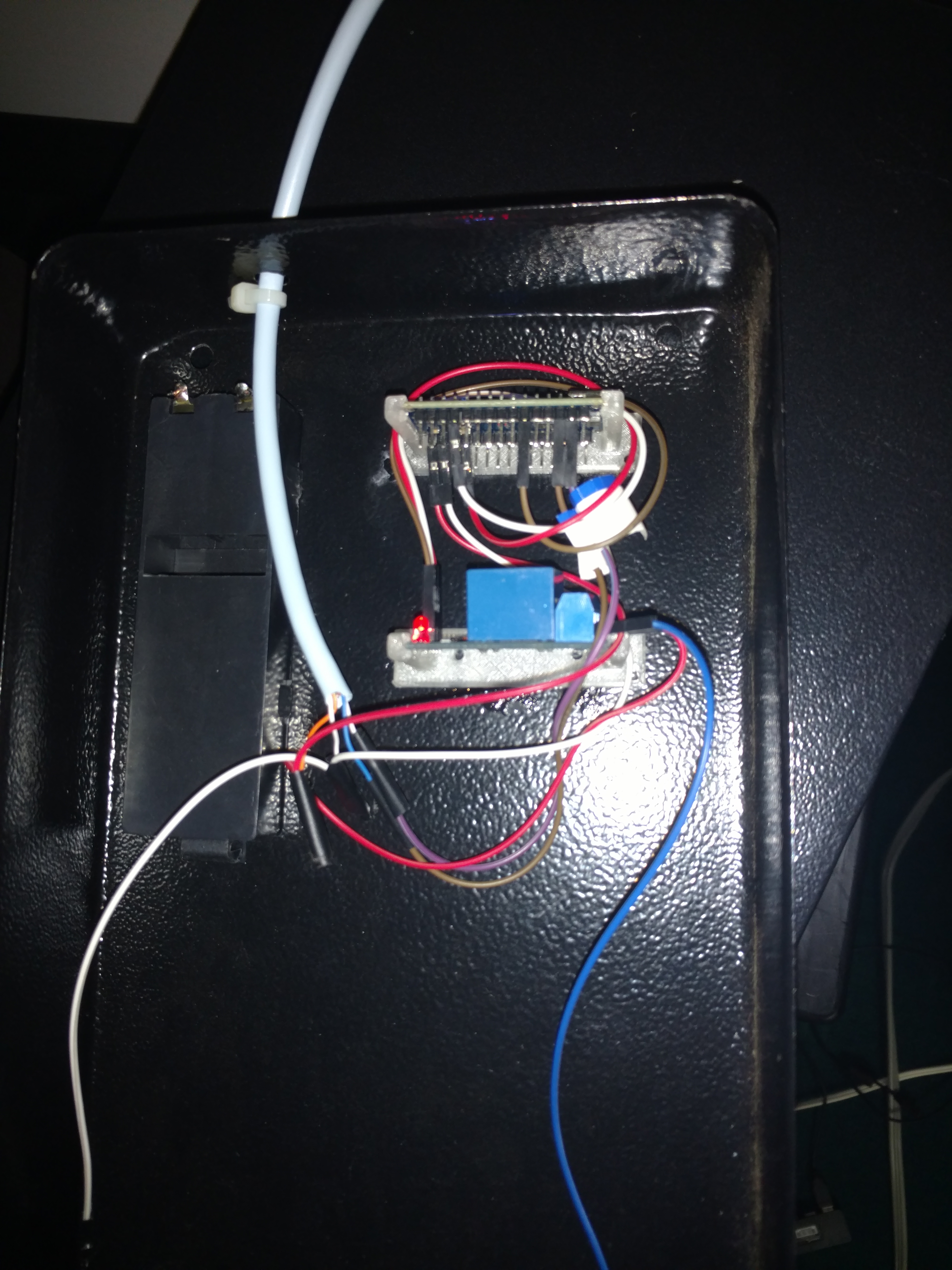
Glue the carriers down. It should be below the battery compartment,
because this is where the old controller board fitted and so there's
space.
Connect the cables.

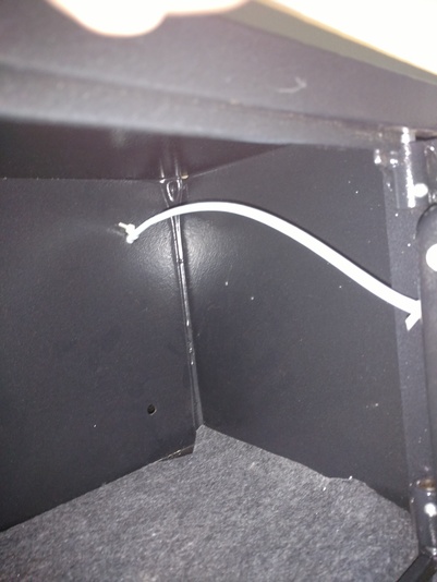
You can see I put a cable tie just before the hole; this is an attempt to
prevent the cable from being pulled from the outside and breaking a
connection.
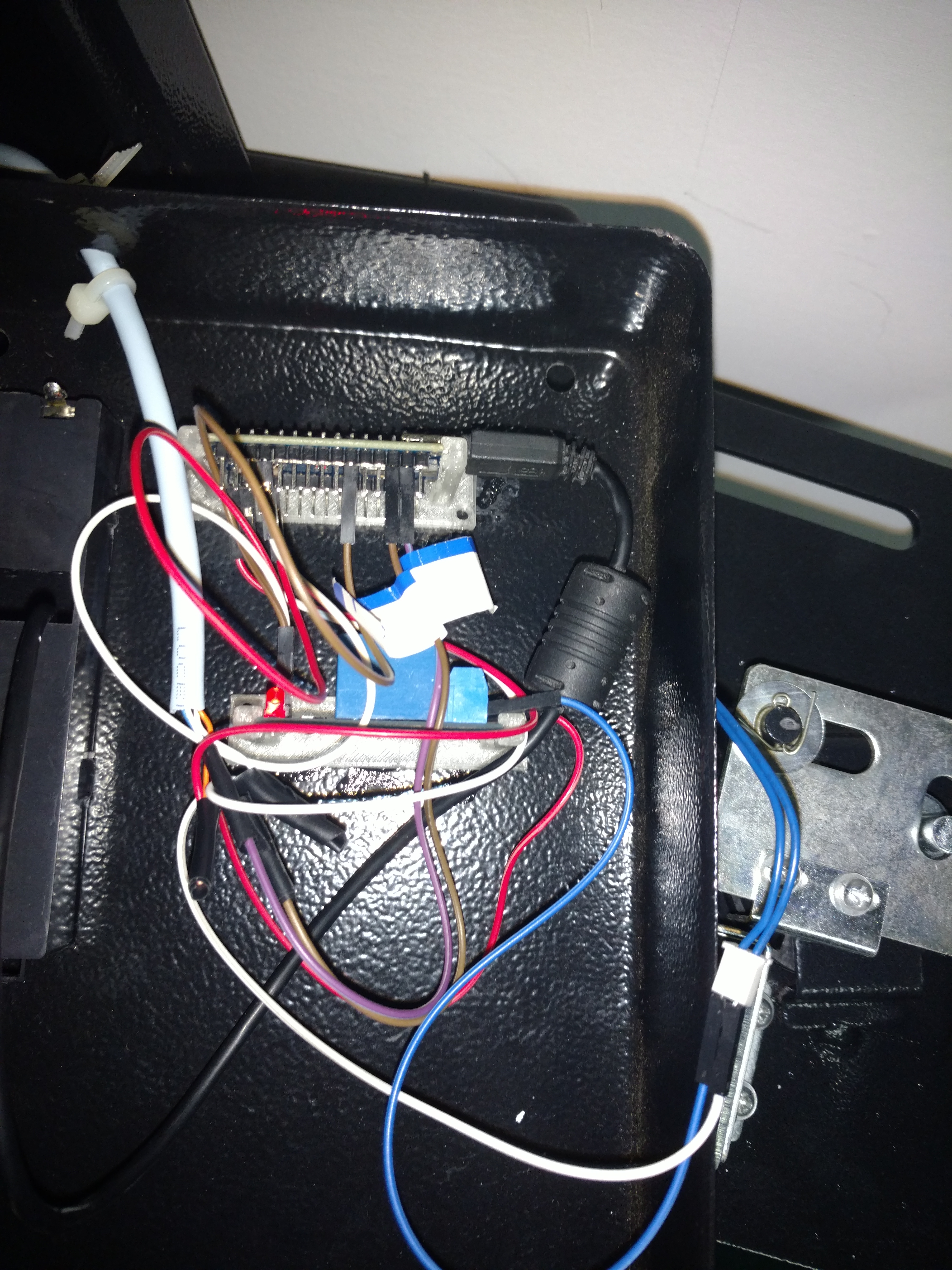
I decided to add a USB cable (and realised I should have oriented the
pieces a different way; there wasn't enough space for it) and poked
the USB cable out through the battery compartment. This allows me to
reprogram (upgrade/bug fix) without pulling the whole thing apart.
The USB cable fits just inside the battery compartment so it's not
accessible from outside unless the door is open.
Test the setup and then screw the cover back to the door. This hides
a multitude of sins and it looks pretty neat!
Arduino software
This sketch should be loaded onto the Arduino. It's
pretty simple and is purely used to control the solenoid. It listens on
the serial port at 9600 baud and will respond to a few instructions.
Each instruction begins with a : character. After the instruction is
another : and then an optional parameter, and then ends with another :
character. No RETURN is needed.
When power is applied the board says "hello" and tells you if the safe
is locked or not. Except for the PING command responses will either
start with OK or ERROR.
-
:PING:message:
Response is PINGACK:message:
Used to test communication
-
:LOCK:password:
Sets the safe to locked state. Can not be used if already locked
-
:UNLOCK:password:
Unlocks the safe... if the password is correct! Allows for one use of OPEN
-
:CLEAR:password:
Clears the password and resets the safe to unlocked state.
-
:TEST:password:
Tests the password but leaves the safe locked.
-
:OPEN:time:
Opens the solenoid for "time" seconds (default to 5 seconds)
-
:STATUS::
Returns if the safe is locked or unlocked
Testing
I use Linux and the kermit command, but any terminal emulator
would work. The Arduino does not echo what you type, so I've turned on
local echo mode so I can see what I'm typing. I run the kermit
command and then apply power to the safe. You should see the onboard LED
start flashing once a second while it is waiting for commands. (You won't
be able to see this when the safe is closed and locked, but it's useful
while testing the setup). Remember, there's no need to press RETURN
(indeed you'll get an error if you do).
% kermit -l /dev/ttyUSB4 -b 9600
C-Kermit>set local on
C-Kermit>c
Connecting to /dev/ttyUSB4, speed 9600
 Escape character: Ctrl-\ (ASCII 28, FS): enabled
Type the escape character followed by C to get back,
or followed by ? to see other options.
----------------------------------------------------
OK Safe code started.  Safe is unlocked
:ping:1234:PINGACK:1234:
:status::OK Safe is unlocked
:lock:12345:OK Safe locked
:status::OK Safe is locked
:open::ERROR State is locked
:unlock:9876:ERROR Wrong password
:unlock:12345:OK Safe unlocked
:open::OK opening safe for 5 seconds
OK opening safe for 4 seconds
OK opening safe for 3 seconds
OK opening safe for 2 seconds
OK opening safe for 1 seconds
OK completed
When the open command is run then the solenoid should click open and
the safe door can be opened. At the end of the time the solenoid
should click back again, allowing you to lock the door closed. The
open command is also the only command that will return more than one
line of results.
Main code
The safe code simply provides control over the solenoid. It effectively
just replaces the front panel keypad. But since it's over a serial
port it means that we can write programs for our PC to control it
(eg pick a random password). The limits of what the program can do are
bounded purely by your imagination. Because the password is stored inside
the Arduino, and that's inside the safe, you can't cheat... except in one
way; you could write a program that will try and brute-force guess the
password. Now the safe can handle 100 character long passwords. Let's
assume a standard A-Za-z0-9 character set and 100 guesses per second,
that's 62^100/100 seconds needed to check every combination. Or
54962310687024123417094664250549034290648513960863640477969506441019257048928403777873869677398592797712143671632918789906836353961913573996848721028517534334752940880822 years.
Good luck with that :-) I might modify the safe code to sleep for
30 seconds after 3 failed attempts to make it even harder...
My plan is to write a web server interface that will allow for local
control or (if you're clever) for a remote keyholder to set passwords.
Your keyholder could unlock the safe remotely while you are on a webcam,
and then re-lock it after cleaning, for example.
The PC software is now available here.